Building a Speedometer for my Dog
I built a Persistence of Vision speed indicator for my dog, using an Arduino, a few LEDs and resistors, and less than 40 lines of code. This is the story of the process and results.
The beginning
I’ve had an arduino for ages, but didn’t really have a project that I wanted to build. Then, at the end of 2012, I had an idea: Why not build something interesting and a little bit crazy? Thus, the dog speedometer was born.

Our dog, Pippi, a Jack Russell of sorts, is always brimming over with enthusiasm and happiness. One day, watching her tearing through the garden, I started thinking about how to measure how fast she runs.
There are many ways to measure speed, but I wanted something very simple with a visual indication. I’ve always liked Persistence Of Vision displays, and thought that showing her speed using a POV display would be cool. Since a POV display has to be attached to something that’s moving, it would work well if the display could show how fast it’s going.
The idea
I’m always looking for ways to get functionality out of the minimum amount of hardware, so options like gps and inertial measurement were right out.
Slowly the idea formed that the display itself could be the speed measurement.
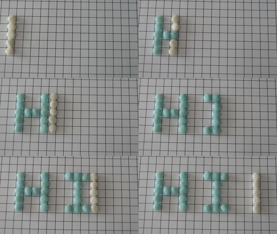
A POV display works by moving a line of LEDs and lighting them up with exact timings so that they leave an after-image in your sight. The stop-motion example above shows the white line of sweets representing the LEDs and the blue ones showing the after-image if they are lit up in sequence.
Since it’s a POV display, could I skew the line of leds and time the signals so that they only line up at specific speeds?

This stop-motion sequence shows the basic idea: Skew the line of LEDs to an arrow shape. All the arrows are flashing the same pattern with the same timing, but they are moving at different speeds. The middle line is moving at a speed that results in a perfectly straight line. The top line is moving at half that speed, and the bottom line is moving at 1.5x the speed.
Experimentation
There was a regular weekly maker meetup at the local university. At one of these nights, I implemented a simple version of the board to demonstrate the idea.
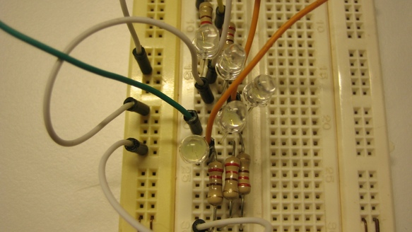
The initial build was very crude, built on a breadboard.

I programmed it to show the numbers 1-9 in sequence. Each number is shown at a slightly different rate, so that the undistorted number would be the speed I was moving at. Breadboard spacing is 1/10th of an inch and the LEDs are placed 2 holes apart, so an 18ms delay is roughly equivalent to 1 km/h.
 1# The binary sequence to output to the port for each number.
 2
 3byte one[] = {B0, B10001, B1010, B100, B0};
 4byte two[] = {B10001, B10011, B10101, B01100, B100};
 5byte three[] = {B100, B100, B10101, B11011, B10001};
 6byte four[] = {B100, B1100, B10100, B1010, B10001};
 7byte five[] = {B10001, B11001, B10101, B110, B100};
 8byte six[] = {B100, B1110, B10101, B10011, B10001};
 9byte seven[] = {B0, B0, B10100, B11010, B10001};
10byte eight[] = {B100, B1110, B10101, B11011, B10001};
11byte nine[] = {B100, B1100, B10101, B11011, B10001};
12byte zero[] = {B100, B1010, B10101, B11011, B10001};
13
14int i = 0;
15
16# Prep the output port
17void setup() {
18    DDRD = 0xff;
19};
20void loop() {
21
22    # One is shown at 18ms delay.
23    for (i=0; i<5; i++) {
24        PORTD = one[i]; delay(18);
25    };
26
27    # Two is shown at 9ms delay.
28    for (i=0; i<5; i++) {
29        PORTD = two[i];
30        delay(9);
31    };
32
33    # ------------------- etc.
The program above is shortened for clarity. Note that those binary sequences are the reversed ones (see the inverted arrow of the next build).

I took it out to a dark corridor and did a few tests. I walked along at different speeds, with the result showing in the separate lines. The top one shows a faster walk.
Note that in all these lines, the flashing sequence is exactly the same. What you see depends on the walking speed.
Also, at this point I did not know about the Arduino microseconds timer, so it was all milliseconds.
More permanent build
Having proved that it worked in principle, it was time for a bit more robust build.
Some things I noticed from the test build:
- The arrow idea works, but it points the wrong way. I would like the skewing to point towards the correct value, not away from it.
- The arrow shape needs to be more pronounced, otherwise the result is very skewed in the slow direction, but almost straight in the fast direction.
- Since a slow speed indication takes up a lot of space, it’s best to pick a range of expected speeds so that the slowest speed does not take up several meters to render.
For the final run I chose a speed range of 10 to 30 km/h. Showing every value in that range would also take up too much space, so I picked a simple scheme: I would show a vertical line representing 10km/h, the number 15 to represent 15km/h, another vertical line for 20km/h, 25km/h as a number, and a line for 30km/h.
It should look something like this:
1 15 1 25 1
(but skewed, of course)
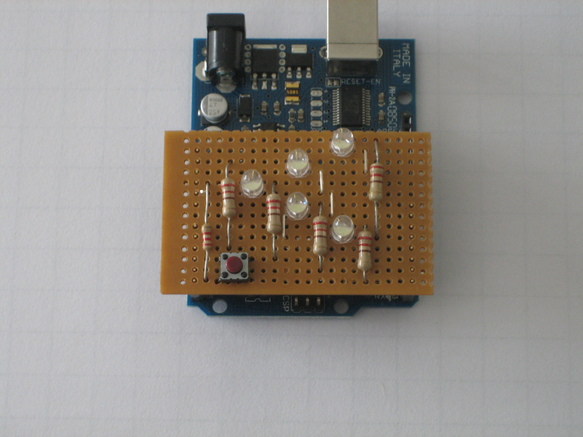
The build itself was done on a simple piece of veroboard. The hole spacing is 1/10th inch, and the build is simple enough for an out-of-practice solderer like me. The button is actually not needed.
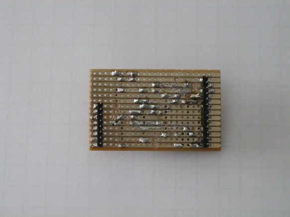
If the veroboard build uses only a few pins, you can leave out the weirdly-spaced ones on the one row of the Arduino, so you don’t even have to bend any pins.
I have larger photos and v2 code up on github:
https://github.com/jbeyers/speevo
Test run
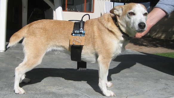
Pippi was not crazy about wearing the harness. We had real trouble getting her to run while wearing it.
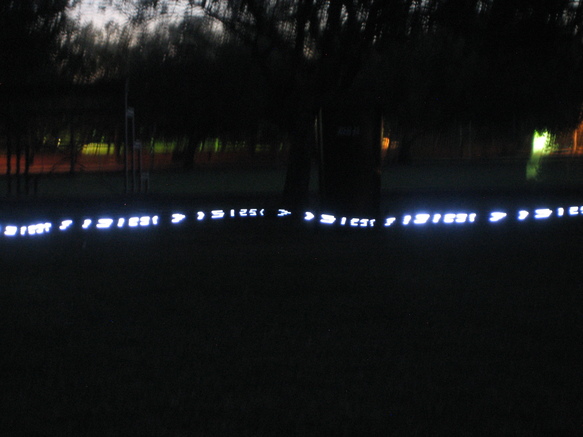
Success! Running at about 20 km/h.
Results
- It works! You can get a good speed indication to within 1 km/h.
- You need a camera to really see the result clearly. The speed shown is too slow for a good POV effect.
- If you want to use a normal camera, you have to shoot in low light so you get a long exposure. I used CHDK on a Canon camera to get a long enough exposure.
- Obviously, this only works with an object moving from left to right.
- It should work well on bicycles, rc cars, drones and merry-go-rounds.
- Less than 40 lines of code in total. This is a really simple project.
Video
I made a demo video of the speedo in action. Not on the dog, but on a special rig I built to show the principle.
Future
I had planned to do a custom board design and some other refinements, but I got distracted with some other projects. I may still do this.
UPDATES!
I got a few mentions on the web for this post:
I also posted this as a project on a few places: